The aim of this article is to explain the microphone specifications and their relevance for the sound engineer, when choosing microphone type. Obviously the intention with specifications in general is to be able to compare the product features and the quality. The international standard committees are aiming to provide the measurement platform which should ensure the maximum conformity among the manufacturer's submitted specifications, but still the relevance of the different specifications might not be obvious to the user, - and can he/she be sure if the specifications are directly comparable?
Frequency response
The term "frequency response" is used in general by both sound engineers and microphone manufacturers when describing a certain microphones ability to transform complex acoustic signals into electric signals. The frequency response will indicate if the microphone will handle the sound source faithfully or if it will introduce a coloration. Therefore information about the microphone's frequency response is probably the most important indication of a microphone's electro-acoustic quality and should always be submitted by the manufacturer either as an individual measurement or as a typical response curve also stating the tolerance field. But the microphone will normally change frequency response according to the direction of the sound source and even according to the acoustic environment it is placed in. Therefore serious microphone manufacturers normally states more than one frequency response for a microphone in order to give a more differentiated picture of the product. This article will describe the different professional terms used in relationship with a microphone's frequency response plus the measurement method used to reveal these specifications.
Measurement conditions and techniques
In order to compare microphone specifications between manufacturers, it is vital to understand the conditions the manufacturer rely on when measuring the microphone specifications. The following is an exceptional glance into the microphone laboratory. - A guided tour through the measurement techniques used to reveal the frequency responses of the studio quality microphone. Reliable specifications can only be obtained if the correct measurement conditions are present in the laboratory. The serious manufacturer's credibility totally rely on the measurement facilities in his laboratory:
1. Accuracy of the measurement equipment
2. Calibration of the measurement equipment
3. The laboratory's acoustical enviroment
4. Quality and calibration of the reference microphone
International and national standard committees such as the IEC (International Electrotechnical Commission), the German DIN (Deutche Industri Norm) and lately also the AES (Audio Engineering Society) are working seriously for better standards and for higher conformity between the microphone manufacturer's submitted product specifications. This should give the sound engineer a more reliable platform to evaluate the quality between the different brands and products from. But nobody is forcing the microphone manufacturers to submit to these standards and there is no international organisation who check the specifications. The most serious and comprehensive microphone standard of today is probably the IEC 268-4 (Microphones for sound equipment) and the IEC 1094-4 (Measurement microphones). Here we find descriptions of various methods of taking frequency response curves plus information about the overall accuracy we can expect from the different methods:
Point-by-point frequency method in free field
The frequency response curve is recorded by measuring the output level of the microphone at selected frequencies only. Great care is needed to ensure that all significant peaks and troughs of the frequency response curve are explored. The graph shall clearly indicate the points taken and free field conditions needs to be obtained in an anechoic room.
Continuous sweep frequency method in free field
This method also needs an anechoic room to emulate a free field, but here a sweep generator is synchronised to an automatic level recorder and the frequency response curve is drawn directly on a special pre-printed curve paper. The speed of the sweep has to be noted on the curve paper and has to be slow enough to ensure that the resulting curve does not deviate from that which would be obtained under steady state conditions. For example a high sweep speed could result in a relatively flat frequency response curve, not revealing any possible irregularities a microphone frequency response could exhibit. The measuring equipment used needs to be capable of automatically maintaining the requisite sound pressure level over the frequency range concerned.
In the two methods described above engineers rely on the quality of the anechoic room which in most cases have problems at very low frequencies. Therefore it necessary to use a different and more reliable method to explore the low frequency qualities of the microphone in question.
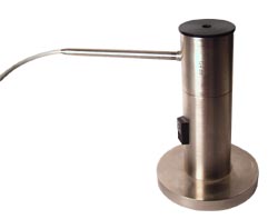
Very low frequency response method in pressure calibrator
Pressure calibrators are extremely important measurement tools for the serious microphone manufacturer. The pressure calibrator is a pistonphone (a rigid enclosure fitted with a piston or a quality loudspeaker inside) and can give important information about a microphone's behaviour under extreme conditions like very high (distortion free) sound pressure levels or at very low frequencies. The acoustic conditions inside the calibrator are monitored via a reference microphone to ensure that the level is correct and that the acoustic field is distortion free. Inside the calibrator the diaphragm of the test microphone will couple directly to the piston via the air. The movements of the piston can be controlled using extremely limited signal power. A pressure calibrator is air tight when both the test microphone and the reference microphone is fitted. This means that even extremely slow movements of the piston will be coupled directly to the diaphragm of the test microphone. Now the perfect conditions for recording a very low frequency response is obtained in the laboratory and by using the reference microphone the level of this response can be matched to that of the response obtained in the anechoic room. Please note that this method can only be used with omnidirectional microphones. The low frequency qualities of directional microphones are best recorded in a duct where free field conditions can be obtained at low frequencies.
Time frame frequency response method
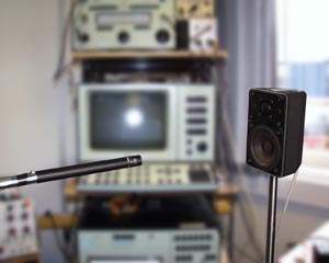
Modern FFT analyser technology makes it possible to measure free field response curves on quality microphones out side the anechoic room using the so called time frame frequency response method. By constantly calibrating the measurement set-up with an extremely linear reference microphone, it is possible to eliminate the response of the loudspeaker and the room in the measurement for higher frequencies (i.e. above 200 Hz). Extremely linear here means linear at least one octave higher than the high roll-off frequency of the test microphone. The reliability of this method is therefore totally dependent on the quality of the reference microphone and of cause also of the accuracy of the FFT analyser equipment. The time frame frequency response method is fast and can be used with both directional and omnidirectional microphones.
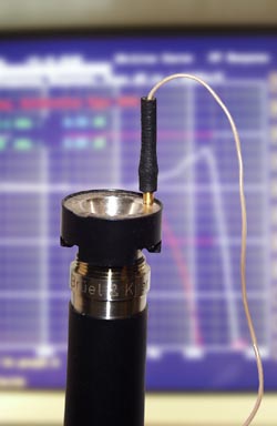
The actuator method for pressure condenser microphones
The far most reliable and accurate measurement method is the so called actuator method, because it is totally independent of special anechoic conditions or the general acoustic environment in the laboratory. The actuator is a precision made device which uses a quite strong electrostatic field to shake the diaphragm. It is put directly in front of the condenser microphone diaphragm in place of the protection grid and the electrostatic field between the actuator and the diaphragm is created by 800V DC plus a sinusoidal tone sweep. There is no acoustic signal involved and therefore no need of creating a special acoustic field or anechoic conditions, but the response curve obtained by the using this method is somewhat different from the well known on-axis response as the influence of the front grid is not measured. However a relatively simple algorithm can compensate for the difference, which therefore makes this method well suited for systematic frequency response measurements in a serial production.
The actuator method can only be used with pressure (omnidirectional) microphones.
The quality of the microphone laboratory
The most serious and comprehensive microphone standard of today is probably the IEC 268-4, which the most serious microphone manufacturers submit to. This standard is so comprehensive, that it describes the quality level of a microphone laboratory and the measurement conditions which the credibility depend on. IEC 268-4 specify a list of rated conditions which should be present in the laboratory to comply with the standard. Here are some of the most important conditions - rewritten in relatively plain English: The microphone should be connected to a minimum permitted load impedance, which normally is specified by the manufacturer or at least 5 times the internal microphone impedance also specified by the manufacturer.
If the microphone needs a power supply, this shall be a rated power supply as specified by the manufacturer. For pre-conditioning the microphone shall be switched on for a period of time specified by the manufacturer or at least 10 minutes before measurements are made. In the DPA laboratory we are using a HMA4000 Microphone Amplifier for the hi-voltage microphones and a specially designed phantom power unit Type 113178 (not available for sale) for all P48 microphones.
The microphone is placed in a free sound field, the waves having zero degree incidence with respect to the reference direction.
The undisturbed sound pressure level (in absence of the microphone) in the sound field at the reference point shall be sinusoidal and set at the level 94 dB re. 20 mPa (this is equivalent to a sound pressure of 1 Pa). A calibrated reference pressure microphone shall be used to measure the sound pressure level.
The ambient pressure and the ambient temperature shall be stated and within given limits according to IEC 268-1.
