Any microphone is only as good as the cable load allows it to be. So how can you get a good recording result if you have a long cable run to your control room and would like to record loud sound sources?
As far as the cable length is concerned, a microphone's frequency response depends on three factors:
The cable load (the cable length)
The sound pressure level of the sound source
The power supply for the microphone preamplifier
Among other technical details, cable manufacturers normally state two different cable capacities per meter: The conductor to conductor capacitance Ccc and the conductor to screen capacitance Ccs. Typically the value are:
Ccc = 100pF/m and Ccs = 200pF/m.
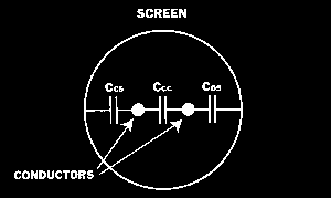
Fig 1: The configuration of the capacities inside a standard balanced microphone cable.
Figure 1 shows how these capacities are placed inside a standard balanced microphone cable. It can be shown that total capacity load per meter is: Cres = (Ccs+Ccs)//Ccc = 100pF/m
It is this value which causes the problems when we are designing the output stage of the preamplifier, or when you, as the user, would like to use a microphone together with a long cable.We have chosen to compare microphones with transformer outputs with a microphone amplifier, because this will be most fair to the microphones as far as cable drive capability is concerned.
The Types 4006 and 4007 are both phantom powered microphones (P48) using identical transformer balanced microphone preamplifiers. The table in Figure 2 shows the peak open circuit output levels in mV and dBm for the Type 4006 and Type 4007 for a given peak incident sound pressure level. The effect of the cable load on the output of the microphones are shown in Figure 3
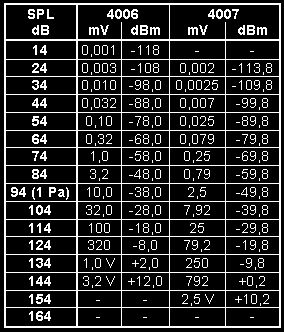
Fig. 2: Nominal peak output levels of the Types 4006 and 4007 for a given peak incident sound pressure level.
Figure 3 shows that you cannot expect a full frequency response at any level of sound without distortion, if you also want to run long cables to the microphones. Figure 3 is not a frequency response curve, but should be read as a graph showing the distortion free area of the microphone when loaded with a specific cable length.
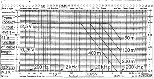
Fig. 3: The effect of various cable lengths on the frequency response
of the preamplifier in the Types 4006 and 4007. The curves represent
1% distortion.
In our favour is the tonal balance of music signals in general, where we can expect at least a -3 dB/octave slope on the overall music spectrum. This gives us much less energy in the higher frequency area to handle than in the lower and mid range.
This is true as far as we are talking about microphones not being used in close miking situations with loud sound sources such as horns or percussion. Here we can expect much more sound energy in the higher frequency area and, of course, much higher peaks in the sound pressure levels in general. Figure 3 then tells us, that the microphones cannot be expected to run long cables and still capture the full distortion free frequency response of the sound source. The phantom power system will start to limit the microphone's capability to drive the cables with full frequency response and it will take it out on the high frequencies first. We need a special powered line driver to handle this situation.
The answer is high voltage microphones together with the HMA4000 High Voltage Microphone Amplifier. This unit is mains powered and is equipped with a highly efficient dual line driver capable of driving long cables without loosing frequency range.
The Figures 4 and 5 are comparable to the Figures 2 and 3, but this time we let the HMA4000 drive the cables.
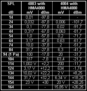
Fig. 4: Nominal peak output levels of the HMA4000 when used with the Types 4003 and 4004 for a given peak incident sound pressure level.
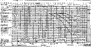
Fig. 5: The effects of various cable lengths on the frequency response
of the line driver in the HMA4000. The curves represent 1% distortion.
Again it is important that you do not see the Figure 5 as a frequency response curve, but as a graph showing the distortion free area of the microphone amplifier when driving various cable loads at various levels of output.
When you compare Figure 3 and Figure 5 the conclusion obviously speaks for the High Voltage Microphone Amplifier solution. A mains powered microphone amplifier placed close to the microphones is more qualified for driving long cables without distortion than phantom powered microphones.